This tutorial was created to help people with the disassembly of the Rio Chiba MP3 player and identification of some internal components. I am not an employee of Rio, Mouser, ALPS or any other company mentioned in this article. I own the Cali, Chiba and Nitrus MP3 players made by Rio and have posted this information so others can learn from my experiences.
After I took apart my Cali and posted the information, I got curious as to what was in my Chiba. Thus, this page was born.
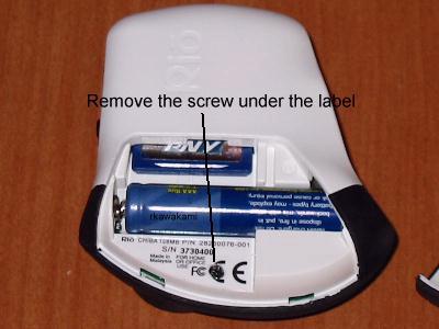
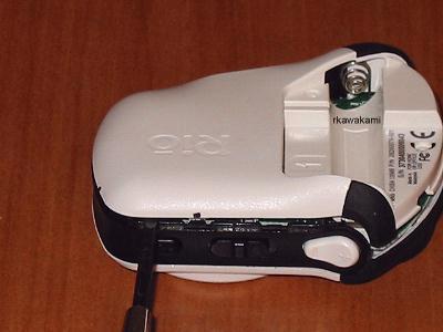
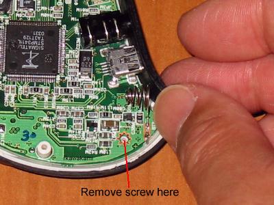
Remove the battery cover, battery and any SD/MMC memory card. There should be a small label with the unit's serial number near the edge of the battery cover. Remove the label, or simply cut away the part of the label that covers the small Phillips screw. Remove the screw.
The second step is to carefully pry apart the shell of the Chiba. There are several 'tabs' around the Chiba's case which keep the two halves together. I have marked the outside of mine with dots so you can see where they are:
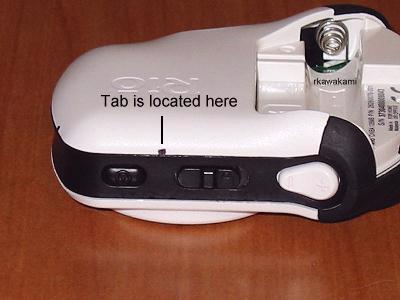
Starting from the battery compartment area, you can put a small flat-bladed screwdriver into one of the rectangular slots near the screw in Figure 1 and pry the pieces apart just far enough to put a fingernail or small screwdriver between the two halves. Work TOWARD the volume switches, until you get to the first tab as seen in Figure 5.
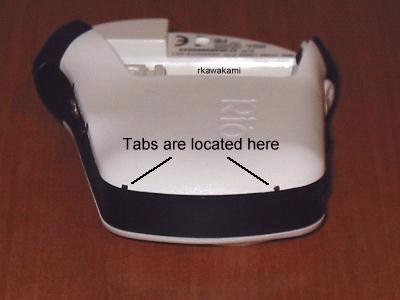
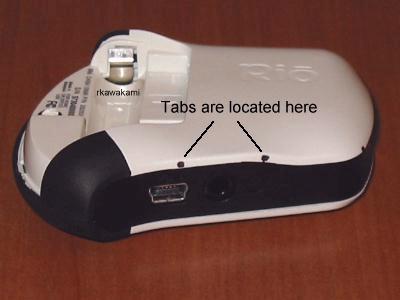
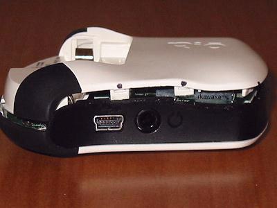
When you get to the areas where the tabs are, a little more extra effort may be needed to release the tabs. What works for me is to insert a small screwdriver into the crack and "twist" the halves apart. Continue to work around the case past the power switch, headphone jack and USB port until you have the case apart.
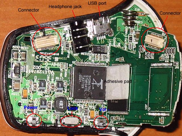
Lift off the back side of the case, making sure you clear the battery connections. This is what you will see when you remove the case:
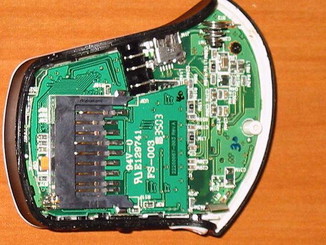
Like the Cali, the Chiba internals consists of two printed circuit boards which are mated together through the use of a small connector. However, instead of a small screw holding them tight, the Chiba has a piece of double-sided tape underneath the area where the SD/MMC card is inserted.
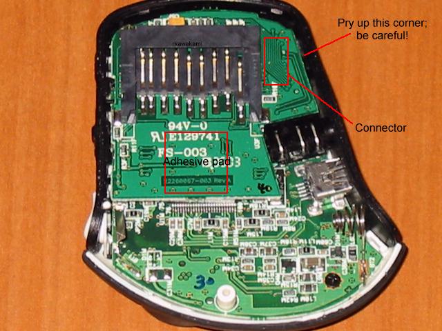
Referring to Figure 8, pry up the corner of the 'memory' board where the connector is, by using a small screwdriver. Be very careful on how far and how hard you insert the screwdriver past the edge of the board; you do not want to damage the very tiny pins on the connector. When you have separated the connector, continue to lift up the board up until you have removed the adhesive pad from one of the 'chips'.
As you can see in Figure 9, this is a 128MB Chiba (it's missing the second flash memory on the right side of the picture). One of these days I'm going to try to install another memory device and see if I can turn it into a Chiba 256MB! There are no other important (or easily replaceable) components on this 'memory' board so let's turn our attention to the getting the 'main' board loose.
Looking at Figures 10 and 11, first remove the small Phillips screw. You will see that the black strip of plastic that encircles the case can be detached by pulling up and outward next to the battery '-' connection and USB port.
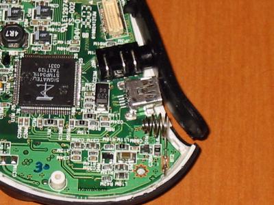
Continue to peel back the strip of plastic past the USB port and headphone jack. When you get to the area where the connector is, you will see a small piece of plastic that holds the board down. Using a small screwdriver, pry the black plastic strip out until the tab allows the board to lift up and out of the case (Figures 12 and 13).
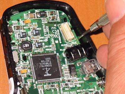
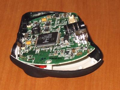
Figure 14 shows the 'front' side of the main board. Here is where you can get access to the 'Menu', 'Volume +' and 'RioStick' switches.
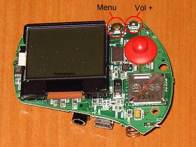
Figure 15 is a close-up of the front side showing the 'Riostick', 'Menu' and 'Volume +' switches.
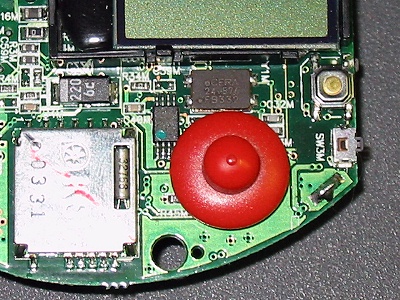
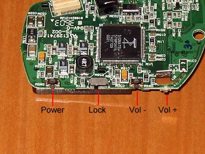
Figure 16 shows the 'back' side of the main board. The 'Power', 'Lock', and 'Volume -' switches are located on this side.
As I have explained on the Cali information page, I have found a source for replacement volume, power, lock, RioStick and menu switches.
| Rio Part: | Volume and Power switches |
| Manufacturer: | ALPS |
| Mfg. Part #: | SKRELBE010 (this is a link to an ALPS .PDF file) |
| Description: | SMD Tactile Switch 3.9 x 3.55 x 1.5mm 220gf with guide bosses (see Note below) |
| Source: | Mouser.com |
| Source Part: | 688-SKRELB (this is a link to a Mouser order page) |
| Note: | Some time prior to Sept 2004, this part was discontinued by ALPS and is superceded by SKRELGE010, a lead-free version (Mouser part 688-SKRELG). "220gf" refers to the amount of pressure required to activate the switch. "gf" means "gram force". ALPS also uses a spec of 2.16N (Newtons) which is an identical pressure. The "guide bosses" refers to the two plastic guide pins on the bottom side of the switch which aids alignment of the switch and provides some (limited amount) of protection from the switch being sheared off through excessive activation pressure. I used the SKRELB switch only because Mouser was out of stock of the newer version. |
| Rio Part: | Lock switch |
| Manufacturer: | ALPS |
| Mfg. Part #: | SSSS811101 (this is a link to an ALPS .PDF file) |
| Description: | SMD Slide Switch SPDT (1 pole, 2 positions) 1.5mm travel, with ground terminals |
| Source: | Mouser.com |
| Source Part: | 688-SSSS811101 (this is a link to a Mouser order page) |
| Rio Part: | RioStick (5-way joystick) |
| Manufacturer: | ALPS |
| Mfg. Part #: | SKRHABE010 (this is a link to an ALPS .PDF file) |
| Description: | 4-directional switch with center push, with guide bosses |
| Source: | Mouser.com |
| Source Part: | 688-SKRHAB (this is a link to a Mouser order page) |
| Rio Part: | Menu switch |
| Manufacturer: | ALPS |
| Mfg. Part #: | SKQGABE010 (this is a link to an ALPS .PDF file) |
| Description: | 5.2 x 5.2mm Low Profile TACT Switch (SMD), 160gf with stem (see Note below) |
| Source: | Mouser.com |
| Source Part: | 688-SKQGAB (this is a link to a Mouser order page) |
| Note: | This information has been placed here following a question that was brought up by a poster to the Rioworld site. From the looks of the switch, I believe that this information is correct. "160gf" refers to the amount of pressure required to activate the switch. "gf" means "gram force". ALPS also uses a spec of 1.57N (Newtons) which is an identical pressure. The "stem" refers to the small, round 'button' that is located on top of the switch which extends the height slightly. |